Shopping Cart
0 item(s) - $0.00FET Driver - 20mm
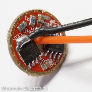
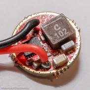
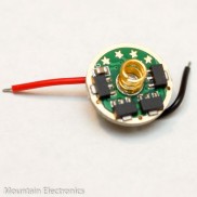
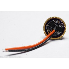
This is a single-sided "direct drive" driver with an ultra low resistance FET. This gives you near-direct-drive performance (limited mostly by your battery, LED, and connections) with the ability to still use lower power levels. This is the ultimate 20mm "hot rod" driver!
All drivers feature fast PWM and come with pre-soldered silicone leads. Unless the option is checked to remove the spring, all drivers also come with a copper braided spring pre-installed.
Why buy this driver? The answer is simple: pure performance and quality. We design, assemble, and test these drivers in-house in the USA using the best components available for the job.
We use only fresh, traceable high-qualtiy components from reputable manufacturers because we want these drivers to work great not only today, but in ten or twenty years from now. All boards are reflowed in a J-STD-020 compliant reflow oven using high-quality solder paste.
Because each driver is hand built and tested, this driver may take up to 10 business days to build, test, and ship.
Standard Clicky Firmware Options
- Standard FET with Memory. This is the most popular option. Equipped with off-time memory, mode changes are intuitive and the light always picks right back up where you left off.
- Mode Levels: Moonlight (Solder #2 to ground) - 2% - 5% - 20% - 50% - 100%
- Standard FET with No Memory. This is the second most popular option. Equipped with off-time no memory, the light will always start on the first mode level after being turned off.
- Custom Mode Levels. Choose your own mode levels. For this option, please enter the following information in your checkout comments:
- 1. Number of light levels: 1-6 (plus moonlight if desired)
- 2. Approximate PWM levels of each mode: Example: (1) 2% - (2) 15% - (3) 40% - (4) - 100%
- 3. Memory or No Memory
Clicky Pin Functions. Soldering these numbered pins to ground will enable these features:
- 2 enables moonlight mode.
- 3 reverses mode order from the standard ascending (low to high) to descending (high to low).
Standard Clicky Firmware Low Voltage Protection. At around 3V under load, the light will blink three times then step down the power level. At around 2.6V under load the light will blink ten times then shut off. This system gives you ample warning and attempts to extend runtime before turning the light off.
Universal guppydrv Clicky Firmware Option (Revs. 1 & 2)
For more information about this firmware, click here.
Electronic Switch Firmware Options
- Standard FET Electronic Switch. This is for use with an external electronic switch, where the driver is always powered, not for use with a standard clicky switch where power is cut by the switch to change modes. This option uses STAR momentary firmware, which allows you to start on either the lowest or highest mode from off with either a short tap or long press of the switch.
- One side of the switch is soldered to ground, the other to the pre-tinned switch pad on the driver (connected to pin 2).
- Custom Mode Levels. Choose your own mode levels. For this option, please enter the following information in your checkout comments:
- 1. Number of light levels: 1-6 (plus moonlight if desired)
- 2. Approximate PWM levels of each mode: Example: (1) 2% - (2) 15% - (3) 40% - (4) - 100%
- Not recommended for use with the Zener Mod option. For 2S+ cell momentary use, check out the LDO 20mm driver instead.
Standard Electronic Switch Firmware Low Voltage Protection. At around 3V under load, the light will step down the power level. At around 2.6V under load the light will shut off. You can override any low voltage shut down by holding down the electronic switch button. This system gives you ample warning and attempts to extend runtime before turning the light off.
moppydrv Multi-Group Electronic Switch Firmware Option
For more information about this firmware, click here.
Zener Mod Option
For use with more than 1 lithium cell on the input. This option allows for 2S-3S cell driving.
- Please remember that this is not a buck or boost driver, so it can't step voltage up or down.
- This means that the input voltage must be closely matched to the output.
- Example: 2 cells in series (8.4V) powering a 6V MT-G2 emitter; 3 cells in series (12.6V) powering 3 XM-L2 emitters in series.
- Zener mod is not recommended for momentary switch applications, since it the driver will constantly draw around 0.01A when power is connected and will drain the cells rapidly while the light isn't in use.
Zener Mod Low Voltage Protection. You can choose between three options for low voltage protection with the zener mod option:
- No LVP: Disable low voltage protection.
- ~6V LVP: The light will begin to ramp down power at around 6V under load. The light will shut off at around 5.5V under load.
- ~9V LVP: The light will begin to ramp down power at around 9V under load. The light will shut off at around 8.25V under load.
Turbo Timer (N/A for guppydrv FW)
A turbo timer may help reduce the chance of overheating. Available Options:
- No Timer
- 30 Seconds
- 60 Seconds
- 90 Seconds
- 120 Seconds
- 180 Seconds
Spring Option
You can check this box if you don't want the copper braided spring installed or included with the driver. This may be useful if you are planning on piggybacking this driver onto another driver, or if you have your own preferred spring you'd like to install yourself.
FREQUENTLY ASKED QUESTIONS:
1. What Is The Input Voltage Range?
- 2.5V-5.5V (non-zener mod)
- This is a "direct drive" driver, meaning it doesn't step up or down voltage that the LED sees. This driver can only be used with a single cells on the input (or multiple parallel cells) and a single XM-L2/XP-G2/XP-L/Nichia/etc. on the output (or multiple LEDs in parallel).
- The MCU (the computer that controls the driver) has a voltage limitation of 5.5V. This means that it can only be used with a single cell unless zener modified.
2. What Are the Downsides vs. The Normal QLITE Driver?
- No Regulation. The amount of light in EVERY mode will drop as the battery drains, where with the normal 7135 driver all modes will be regulated until the battery level drops below the point of regulation.
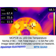
- Heat. While the driver itself doesn't produce very much heat at all (actually runs cooler than a 7135 driver), you need to be aware that not every LED and every setup can handle the heat and current from running direct dirve. Running more current also generally means shorter battery life. This amount of current can also melt switches and springs if they aren't up to the task. It also generally requires LEDs mounted on direct thermal path MCPCBs.
3. What Kind Of Output Can I Expect?
- Output is generally limited by cell selection, LED type, and other connections (such as springs and emitter wires).
This driver was made possible and is heavily inspired by many members of the BLF flashlight community, especially comfychair (initial concept and development), Mattaus (PCB layout and development), JonnyC (firmware), DrJones (firmware), and wight (singe-sided PCB development and advice). If you'd like to learn more about these drivers, and participate in further development, come visit our community at budgetlightforum.com
Write a review
Your Name:Your Review: Note: HTML is not translated!
Rating: Bad Good
Enter the code in the box below:
Mountain Electronics LLC © 2025

