Your shopping cart is empty!
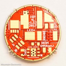
17mm MTN-MAXlp HP 4-Layer Buck Driver PCB - V1.13
Product Code: PCB-MTN-MAXlpHP4L-17MM-v1.13
Availability: 23
Availability: 23
Price: $1.85
Qty:
- OR -
Add to Wish List
Add to Compare
Add to Compare
This is the bare PCB you need to build your own 17mm MTN-Maxlp HP buck driver! DIY parts kit available here.
This PCB is a 4-layer design, with excellent thermal and electrical properties. This PCB will allow you to build the highest performance 17mm LED buck driver possible.
Specifications:
- Low profile
- Configurable for 1A-5.5A peak output, depending sense resistor (4.5A maximum with 6V LEDs)
- At all output levels, the driver needs to have a good thermal path to the pill
- Can be configured for 2S-6S cells (5V-28V), depending on the inductor and capacitors used
- Can be used with pretty much any emitter configuration, provided that the input voltage is greater than the output voltage
- Not recommended for momentary use (high quiescent current drain)
Components Needed:
- RSENSE: Sense Resistor
- 17mm: 2010; 1W or Higher
- Formula: 0.2/R=I
- An Additional Word of Caution Regarding Maximum Amperage. The MAX16820 is a hysteretic converter with a 10% current ripple, meaning that from the center, or average, current set point, the LED will momentarily experience an additional 5% current over the average set current. This means that if you have an LED that can only handle 6A, you need to set the sense resistor at least 5% below that number.
- Example: 6.1A maximum LED, 0.033 Ohm resistor. If all of the components were ideal and perfect, the 0.033 Ohm resistor should give us 6.06A average current. This soundssafe, but it's not. The LED will see peak currents of up to 6.36A, which will blow our theoretical 6.1A maximum LED.
- You also need to take into account the precision of your sense resistor, temperature variances, and several other factors.
- Summary: don't specify a sense resistor that is on the ragged edge of what the LED string can handle.
- An Additional Word of Caution Regarding Maximum Amperage. The MAX16820 is a hysteretic converter with a 10% current ripple, meaning that from the center, or average, current set point, the LED will momentarily experience an additional 5% current over the average set current. This means that if you have an LED that can only handle 6A, you need to set the sense resistor at least 5% below that number.
- ~2A = 0.1 Ohm
- ~3A = 0.068 Ohm
- ~3.4A = 0.058 Ohm
- ~4A = 0.05 Ohm
- CIN: Input Capacitor ***X7R CAPACITORS RECOMMENDED WHERE POSSIBLE***
- 2S-3S cells: 1x 1206 10uF, 16V (or higher); 1x 1206 1uF 16V (or higher)
- 4S cells: 1x 1206 10uF 25V (or higher); 1x 1206 1uF 25V (or higher)
- 5S cells: 1x 1206 4.7uF+ 35V (or higher); 1x 1206 1uF 35V (or higher)
- CMAX: Buck IC Bypass Capacitor
- Leave unpopulated for most applications.
- C_OUT: Output Capacitor
- Optional; can slightly lower LED current ripple.
- 0805 1uF 25V (or higher) X7R (more ripple reduction; can slightly affect switching speed)
- 0805 0.1uF 50V X7R (recommended for most applications)
- CVCC; CMCU: LDO Output/MCU Bypass
- 2x 0603 1uF 16V X7R
- OTC: Off-time Capacitor
- 0603, 1uF, 10V (or higher), X7R
- MCU: MCU attiny13a-MMU
- MAX: Buck IC
- Maxim Integrated MAX16820
- FET: Main Switch N-Channel MOSFET
- NXP LFPAK33
- GD: Zetex ZXDG3009 series.
- D1: Flyback/Freewheel Diode
- 17mm: 2x Diodes Inc. SBR3U40P1-7 or similar.
- Lower forward voltage drop is important, as is reverse transfer capacitance and reverse current leakage at high temperatures.
- 17mm: 2x Diodes Inc. SBR3U40P1-7 or similar.
- L1: Inductor.
- INDUCTOR CHOICE DEPENDS ON SEVERAL FACTORS
- Difference between input and output voltage
- Target switching speed (must stay within ~0.2MHz and ~1.5MHz, but as switching speed increases, switching losses also increase, decreasing efficiency)
- Resistance vs. inductance vs. size (you can usually only have two of these, so you have to prioritize based on the application and size restraints)
- Inductor must be able to handle the peak inductor current without saturating
- MAXIMUM SIZE= ~6.5mm x 6.5mm. Pads are designed to allow many different inductors to fit and work. I have tested this driver with over 10 different inductors with different pad layouts.
- RECOMMENDED INDUCTORS:
- Coilcraft XAL6060 series inductors are the best performance for their size, but they are also the most expensive, at around $2.50 each, plus shipping.
- Other inductors from Abracon, Bourns, and others will also work, but generally have more on resistance for a given inductance and size
- 2S Cells:
- 1A: 15uH-22uH
- 2A: 10uH-15uH
- 3A: 6.8uH-8.4uH
- 4A: 4.7uH-8.4uH
- 3S Cells:
- 1A: 15uH-30uH
- 2A: 8.2uH-15uH
- 3A: 6.8uH-12uH
- 4A: 5.6uH-8.4uH
- INDUCTOR CHOICE DEPENDS ON SEVERAL FACTORS
- R1: 36K 0603 1% (or better)
- R2:
- 2S-3S: 4.7K 0603 1% (or better)
- 4S-5S: 2K 0603 1% (or better)
- RDIM: 100/200 ohm 0603
- PLDN: 360K 0603 (helps with mode switch timing; can also use lower resistance value if faster mode switching is desired)
Firmware:
Use any attiny13a firmware, but one with low voltage protection is recommended. Momentary use not recommended. Capable of up to 20KHz dimming.
Write a review
Your Name:Your Review: Note: HTML is not translated!
Rating: Bad Good
Enter the code in the box below:
Powered By Lumens
Mountain Electronics LLC International Store © 2026
Mountain Electronics LLC International Store © 2026


